FEED Study Introduction
The US Department of Energy (DOE), through its Office of Fossil Energy and Carbon Management (FECM) has funded several Front-End Engineering and Design (FEED) studies for retrofitting existing fossil fuel power plants with carbon capture technology. These comprehensive studies are publicly available on the US DOE Office of Scientific and Technical Information (OSTI) website as part of the knowledge sharing requirements associated with the funding.
This study is our effort to help stakeholders quickly understand the key findings in lengthy reports highlighting methodologies, and unique design aspects that could shape future carbon capture plant designs. Our objective is to provide direction to the most relevant sections of each study.
Retrofittable Advanced Combined Cycle Integration for Flexible Decarbonized Generation
Overview
The FEED study, conducted by GE Gas Power (GEGP), Linde, and Kiewit, examines retrofitting a natural gas combined cycle (NGCC) unit with a carbon capture facility. The host NGCC unit is Southern Company’s Barry Unit 6 Plant. This FEED study focuses on retrofitting a 95% carbon dioxide (CO2) capture system with attention on plant integration.
FEED study link: Retrofittable Advanced Combined Cycle Integration for Flexible Decarbonized Generation
Total CO2 captured: 1.630 MM tonnes/yr
Total As-Spent CAPEX ($MM USD in 2023): $1,716.40
Objective
This summary highlights deviations from “typical” amine-based capture designs. The unique design aspects and studies from this FEED study include:
- Evaluation of exhaust gas recirculation
- Selection of two trains of carbon capture and compression
- Reduction of dissolved non-condensable gases in the CO2 product
- Use of a dry packing bed in the absorber for emissions control
- Inclusion of a regenerator interstage heater to optimize heat duty
- Selection of ion exchange only for amine reclaiming
- Exclusion of an absorber intercooler
- Higher operating pressure of the CO2 regenerator
- Selection of chiller unit for dehydration of the CO2 product
- Antifoam injection in both the lean and rich amine streams
- Exclusion of caustic injection in the direct contact cooler
- Accounting for CO2 losses during compression and dehydration in the CO2 capture efficiency
- Evaluation of the economic impact of carbon capture efficiencies between 90-98%
Exhaust Gas Recirculation Evaluation
What is it:
Capturing carbon emissions from a NGCC unit is challenging due to the low CO2 concentration in the flue gas (approximately 4 mol%). As a solution, this FEED study explored Exhaust Gas Recirculation (EGR), which recirculates a portion of the flue gas back into the combustion air intake of the gas turbine. This process differs from a benchmark facility where the entire flue gas stream from the NGCC unit would proceed to the capture plant. The main benefits is an increased CO2 concentration and decreased flue gas flow rate to the capture facility, resulting in overall capital and operating cost savings.
In this study:
Results from this study indicated that recirculating 40% of the flue gas flow can increase CO2 concentration from 4 mol% to 6.7 mol%, while also reducing the volume of flue gas routed to the capture system by 40%. A reduction in the flue gas flow rate entering the capture facility resulted in smaller diameters required for both the direct contact cooler (DCC) and absorber. An increased CO2 concentration allowed for a shorter absorber as less residence time is required for CO2 absorption into the amine. The study also found that reduced flue gas flow rate and a higher concentration of CO2 in the flue gas lowers amine circulation and reduces reboiler heat duty by about 10%. Additionally, EGR reduces oxygen (O2) concentration, potentially lowering amine degradation and makeup.
The study notes that the addition of EGR reduces the overall cost of capture due to the advantages discussed above. The EGR viability assessment resulted in a net capital cost saving of approximately $43.9MM, in 2018 $USD. The combined impact of EGR to the levelized cost of electricity (LCOE) is a reduction of approximately $1.31/MWh, and the breakeven CO2 sales price is lowered by about $1.96/tonne of CO2 captured. This represents a reduction of nearly 1.6% in LCOE and 2.7% in the breakeven CO2 sales price.
Two Train Carbon Capture & Compression
What is it:
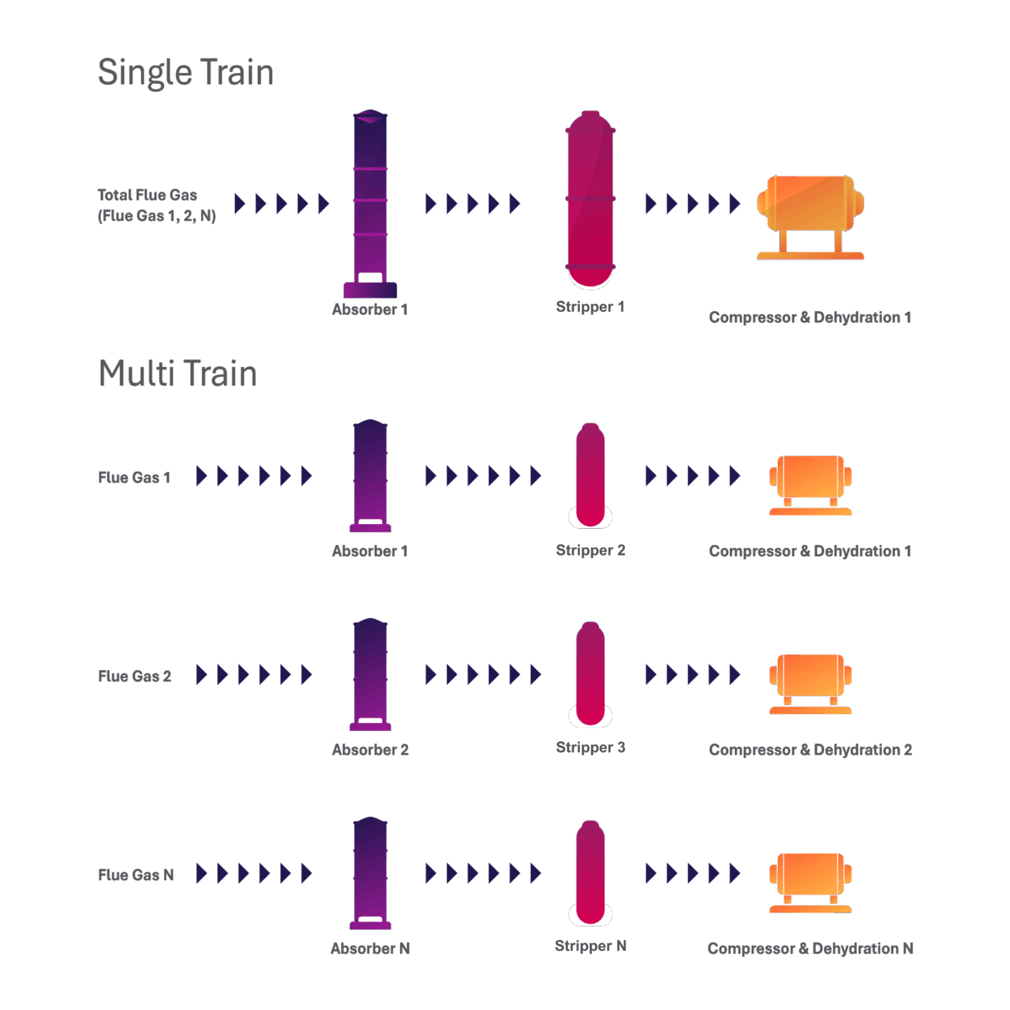
Single-train and multi-train systems are both viable options for capture projects, and an evaluation of the costs and benefits of each system is often necessary to determine the best option. The figures shown illustrate an example of a single-train and a full multi-train system. It is important to note that there are variations of the multi-train system, such as multiple absorbers can be used to feed into a single stripper, which haven’t been captured in the figures.
In this study:
This study selected two carbon capture and compression trains, each coupled with a separate heat recovery steam generator (HRSG).
Additional information:
The choice between these systems is influenced by both site specific and project specific factors. Below we provide a comparison of multi-train vs single-train systems.
Comparison of Multi-Train vs. Single-Train Carbon Capture Systems
| Aspect | Multi-Train System | Single-Train System |
|---|---|---|
| Configuration (in this FEED study) | Two carbon capture and compression trains, each coupled with a separate HRSG | One capture system handling combined flue gases from two HRSGs |
| Prefabrication Potential | Higher – Allows for extensive off-site fabrication | Lower – Larger system components may limit prefabrication options |
| Construction Efficiency | Higher – Faster on-site construction due to shop fabrication | Lower – Longer on-site construction due to size and complexity |
| Project Schedule Certainty | Higher – Due to off-site fabrication of components | Lower – Due to on-site assembly and integration challenges |
| Transportation and Installation | Easier – Due to smaller, pre-assembled modules | More complex – due to size and integration of large equipment |
| Operational Flexibility | Higher – Independent operation of each train allows more turndown flexibility | Lower – Single system may limit flexible operation |
| Reliability and Maintenance | Higher – Online maintenance possible, increased uptime | Lower – Maintenance may require full system shutdown |
| Physical Footprint | Larger – Two systems require more space on site | Smaller – Consolidated system uses space more efficiently |
Reducing Non-Condensable Gases in the CO2 Product
What is it:
The presence of non-condensable gases in the CO2 stream can lead to challenges in transportation and storage. While specific equipment is not commonly included in conventional carbon capture plant designs for removing these gases, incorporating such equipment can enhance the quality of the captured CO2.
In this study:
The final CO2 product specification was <0.5 mol% for the combined concentration of N₂+Ar. To reduce the dissolved non-condensable gases in the CO2 product, this study routed rich amine from the absorber to an amine flash vessel specifically designed to release dissolved non-condensable gases from the CO2-rich amine solution. Here, the rich amine encounters a pressure drop causing the non-condensable gases to flash off, or vaporize, from the rich amine. The flashed vapors are returned to the absorber, while the amine is sent to the regenerator for CO2 removal.
Additional information:
Various sources recommend limiting the total non-condensable components to ≤ 4 mol %. The presence of non-condensable gases in the CO2 product dilutes the CO2 stream, effectively reducing its purity and increasing the overall volume required for compression, transportation, and storage. These gases also alter the boundary of two-phase regions for CO2, shifting it towards higher pressures. As a result, higher compressor discharge pressures are required to ensure the CO2 remains in dense or supercritical phases. This may cause higher capital costs (e.g. for larger compressors and larger pipelines) and may also require larger storage reservoirs. Operating costs may also be higher for compressing, delivering, and monitoring the larger gas volume. Furthermore, the presence of even a small amount of O₂ in the CO2 product can cause a risk of corrosion within transportation pipelines and injection wells, potentially leading to costly infrastructure damage and environmental hazards.
Dry Packing Bed for Emissions Control
What is it?
A wet wash packing bed is typically used to reduce absorber emissions. This involves a conventional wash section in the absorber where wash water passes in a counter-current flow to the flue gas, capturing entrained droplets of amine solution.
In this study:
The introduction of a patented dry packing bed in the absorber design, positioned beneath the wet wash packing bed, enhances emission control in this design. The dry packing bed helps mitigate aerosol-driven amine loss, which is a common issue in carbon capture processes. By reducing amine loss, the dry packing bed improves the efficiency of the carbon capture system and minimizes the environmental impact due to secondary emissions.
Additional information:
This study did not provide full details on the dry packing bed, but more information can be found in the following Linde/BASF presentation: Linde/BASF Update
Regenerator Interstage Heater for Heat Optimization
What is it?
The largest component of operating costs in amine-based carbon capture is the thermal energy required to regenerate the amine. To effectively lower operating costs, most technology licensors incorporate specific designs to ensure optimal heat duty.
In this study:
This study used a unique approach by selecting a regenerator interstage heater. The interstage heater works by utilizing heat from the hot, lean amine exiting the regenerator to raise the temperature of the semi-rich amine at an intermediate stage of the regeneration process. This method helps reduce the overall energy demand for solvent regeneration by utilizing existing process heat for a portion of the heat demand.
Additional information:
Aside from the approach used in this study, other typical methods of heat recovery in an amine-based capture system include the use of mechanical vapor recompression (MVR), and strategic use of heat exchangers within the capture process to reduce the heat duty of the CO2 reboiler.
Ion Exchange for Amine Reclaiming
What is it?
In carbon capture systems that use chemical solvents to absorb CO2, the solvent gradually degrades over time due to heat, oxygen, and impurities in the flue gas. Degradation products accumulate and can interfere with the system’s performance, causing corrosion, foaming, or reduced CO2 absorption performance. Amine reclaiming is necessary in carbon capture systems to remove these degradation products to maintain amine health.
In this study:
This study selected ion exchange resins exclusively for amine reclamation. In general, ion exchange can remove ionic by-products, or heat stable salts (HSS), from the amine. From this process, the study stated they experienced 99% amine recovery.
Additional Information:
Although the ion exchange method removes HSS very well, it cannot remove non-ionic degradation products which are byproducts from the breakdown of non-ionic compounds. Typically, thermal reclaiming units are incorporated into amine-based carbon capture plant design to remove the ionic and non-ionic degradation products. In this process, a small slipstream of the amine is heated in the reclaimer, where the degradation products are separated from the water and amine due to the difference in their boiling points. The water and amine vaporize, and the degradation products are collected at the bottom of the reclaimer and removed. The vapor is then condensed and returned to the main amine loop for reuse. For future studies, a detailed understanding of the reclaiming design is required, particularly to assess whether a thermal reclaimer should be considered to remove both ionic and non-ionic degradation products.
Absorber Intercooler Exclusion
What is it?
An absorber intercooler draws solvent from an intermediate point of the absorber, cools it, and then returns it back to the absorber. The reaction between CO2 and amines is exothermic, increasing the temperature of both the flue gas and the solvent, which reduces the solvent’s capacity to absorb additional CO2. Intercooling lowers the solvent temperature, improving CO2 absorption and enabling a higher rich amine loading. This reduces the solvent flow rate required to capture CO2, which in turn reduces the demand for reboiler steam which can reduce the operating cost. However, incorporating an intercooler involves additional capital costs including the cooler, pump, and absorber internals.
In this study:
An absorber intercooler was not selected for this study, likely based on the results of the cost-benefit analysis.
Additional information:
Amine intercoolers are commonly used in amine-based carbon capture systems to enhance CO2 absorption and reduce energy consumption for amine regeneration. The choice to include an intercooler would be based on a project specific economic analysis.
Higher CO2 Regenerator Pressure
What is it?
The operating pressure of the CO2 regenerator has an impact on the CO2 compression requirements. As the regenerator pressure increases, the temperature and, therefore, energy and cost of amine regeneration increases as well. However, the increase in regenerator pressure translates to a higher inlet pressure to the compressor, decreasing compression load requirements and power costs. An analysis of the relationship between operating conditions of the regenerator and the CO2 compressor helps to determine optimal operating conditions.
In this study:
This study used a regenerator pressure of 3.4 bara. The advantage of operating at this higher pressure is the reduction of CO2 compression energy and compressor capital expenses. However, this also leads to increased regenerator capital costs due to the need for increased wall thickness and raises the reboiler heat duty, thereby increasing operating costs compared to operating at a lower pressure.
Additional Information:
The operating pressure of the regenerator is influenced by two factors, the temperature at which CO2 is released from the amine (CO2 desorption temperature) and the thermal stability of the amine. The thermal stability of the amine dictates the upper temperature limit at which the amine can be safely used without unacceptable thermal degradation. These two factors determine the operating pressure range of the regenerator. Depending on the specific amine properties, typical operating pressures could be in the range of 1.5 – 3.5 bara.
Chiller Unit for CO2 Dehydration
What is it?
The process of dehydration removes water from the CO2 product to ensure it meets the required CO2 product specifications for safe and efficient transportation and storage. The presence of free water is a significant concern for pipeline operations, as it presents challenges such as two-phase flow, hydrate formation, and the dissolution of CO2, which forms carbonic acids. This issue becomes even more problematic in the presence of impurities like nitrogen oxides (NOx), sulfur oxides (SOx), oxygen (O2), and hydrogen sulfide (H2S), which can form corrosive acids such as nitric acid (HNO3) and sulfuric acid (H2SO4).
In this study:
To meet the CO2 product moisture specifications of less than 45 lbs H2O/MMSCF (948 ppmv), a chilled unit was selected for system dehydration. This system works by cooling the CO2 gas using a refrigeration system. The cooling process lowers the temperature of the gas, causing water vapor to condense into a liquid. The liquid water is then separated from the CO2 gas stream.
Additional Information:
In addition to chilled dehydration, several other methods are also commonly used, such as desiccant adsorption, triethylene glycol (TEG) absorption, and mechanical membrane permeation. Chilled dehydration currently has limited application in CCS projects compared to common absorption and adsorption technologies, possibly due to project specific cost-benefit analysis and CO2 product specification. Below is a comparison of various methods of dehydration using adsorption and absorption (Drax BECCS Project – CO2 Compression and Dehydration Unit Report, 2021).
|
Adsorption: |
Adsorption: |
Adsorption: Molecular Sieves |
Adsorption: TEG |
|
|---|---|---|---|---|
| Readiness | TRL 9 (Commercial) | TRL 9 (Commercial) | TRL 9 (Commercial) | TRL 9 (Commercial) |
| CAPEX1 | 100% | 100% | 100% | 66% |
| OPEX1 | 122% | 100% | 165-225% | 33-66% |
| Operability |
Desiccant life = 2 yr |
Desiccant life = 5 yr Agglomerated clumps Sensitive to contaminants |
Desiccant life = 3-4 yr Agglomerated clumps Sensitive to contaminants |
TEG entrainment in CO2; Lower CO2 capture rate (0.2% potentially vented) |
| Reliability | Stable process with potential operability issues | Stable process with potential operability issues | Stable process with potential operability issues | Stable process with potential operability issues |
| Turndown | 30% Turndown | 30% Turndown | 30% Turndown | 30% Turndown |
| Footprint | Smaller than adsorption | |||
| Risk | Proven with CO2 | Proven with CO2 | Proven with CO2 | Proven with CO2 |
1 CAPEX and OPEX values are taken as a percentage of the Adsorption: Silica gel scenario costs as a basis for comparison.
Antifoam Injection in Lean & Rich Amine Streams
What is it?
Pure aqueous amine solvents do not foam. Foaming in amine systems is caused by the presence of contaminants such as condensed hydrocarbons, suspended solids, amine degradation products, or other surface-active agents like lube oil and corrosion inhibitors. Foaming leads to high pressures, increased amine carryover, and reduced amine absorption and regeneration efficiency within a system.
In this study:
This study chose to inject antifoam into both the lean amine entering the absorber and the rich amine entering the regenerator.
Additional information:
Antifoam injection in either the absorber or regenerator is standard practice for controlling foaming.
Caustic Injection Exclusion in Direct Contact Cooler
What is it?
Caustic injection in the direct contact cooler is typically used to reduce the levels of sulfur dioxide (SO2) in the flue gas stream. SO2 can potentially react with amine solvents and form heat stable salts (HSS) if present in the flue gas entering the absorber. This formation of HSS increases the amine reclaiming requirement, which leads to higher operating costs.
In this study:
Caustic injection in the direct contact cooler was not selected for the study, as no sulfur oxides (SOX) were specified in the flue gas.
Additional information:
Pipeline-quality natural gas typically contains very low levels of sulfur, resulting in minimal SOx formation during combustion. As a result, SOX concentrations in the flue gas are generally very low. However, it is important to have deep understanding of the flue gas components to accurately assess their potential impact on system design and operations. It is recommended to minimize SOX concentrations prior to the CO2 absorber to reduce amine solvent degradation and the formation of HSS.
CO2 Losses in Compression & Dehydration
What is it?
The capture efficiency refers to the amount of CO2 removed from the flue gas entering the capture plant. Capture efficiency can sometimes be misunderstood if not defined clearly. For example, a capture efficiency of 95% may imply that 95% of the CO2 in the inlet flue gas is routed to compression and dehydration, or that 95% of the CO2 in the inlet flue gas is delivered to the pipeline or other transportation method. The former does not account for potential losses of CO2 in the compression and dehydration trains.
In this study:
This project defined 95% capture efficiency to mean delivery of the final product to the pipeline, which includes any potential CO2 loss from compression and dehydration.
Additional information:
This study included a chilled dehydration unit where CO2 losses are expected to be minimal because the chilled media and the CO2 stream are not in contact. However, in cases where a TEG dehydration system is used, small amounts of CO2 may be lost through the TEG regenerator stack vent as the TEG is in direct contact with the CO2 stream. Another study, CO2 Compression and Dehydration Unit Report, has shown that there may be approximately 0.2% of CO2 loss from the TEG regenerator stack vent.
Economic Impact of 90-98% Capture Efficiency
What is it?
The capture efficiency refers to the amount of CO2 removed from the flue gas stream sent to the capture plant. Most amine-based technology licensors can design for 90-95% efficiency. Achieving efficiencies beyond this level is technically possible, but further analysis can determine if the additional capital and operating costs associated with higher capture efficiency result in a net benefit.
In this study:
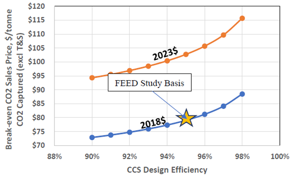
This study evaluated the impact of capture efficiency on the break-even cost of CO2. A capture efficiency of 95% was used as the baseline for the FEED study. To achieve efficiencies greater than this, the solvent circulation flow rates, the specific steam consumption (lb. of steam per lb. of captured CO2), and the CCS equipment size and cost are expected to all increase at near exponential rates. That is, the incremental cost of going from 96% to 97% capture efficiency will be substantially greater than the incremental cost of going from 95% to 96% capture efficiency. The pre-conditioning (CCS direct contact cooler) and the post-capture CO2 compression costs and auxiliary loads will increase at rates proportionate to the increase in CO2 capture efficiency. Figure 1 illustrates the results of this study.
Additional Information:
The Global CCS Institute published information on the CO2 capture fraction in the publication Advancements-in-CCS-Technologies-and-Costs-Report-2025.pdf.
Learn more about BECCS with our BECCS 101 resource.
The CCUS Insight Accelerator (CCUSIA) is a partnership between the Government of Alberta and the International CCS Knowledge Centre to accelerate and de-risk CCUS by sharing knowledge and developing insights from projects.