FEED Study Introduction
The US Department of Energy (DOE), through its Office of Fossil Energy and Carbon Management (FECM) has funded several Front-End Engineering and Design (FEED) studies for retrofitting existing fossil fuel power plants with carbon capture technology. These comprehensive studies are publicly available on the US DOE Office of Scientific and Technical Information (OSTI) website as part of the knowledge sharing requirements associated with the funding.
This study is our effort to help stakeholders quickly understand the key findings in lengthy reports highlighting methodologies, and unique design aspects that could inform future carbon capture plant designs. Our objective is to provide directions to the most relevant sections of each study.
Carbon Capture Design and Costing: Phase 2 (C3DC2)
Overview
This FEED study examines the retrofit of a commercial-scale post-combustion carbon dioxide (CO2) capture facility onto a coal-fired power plant. This was conducted by ION Clean Energy in collaboration with Nebraska Public Power District (NPPD), Sargent & Lundy (S&L), Koch Modular Process Systems (KMPS), and Siemens Energy. For the study, Gerald Gentleman Station’s 700 MW Unit 2 (GGS2) was the host facility, located in Nebraska, USA. The study focused on retrofitting a 90% CO2 capture system at full load and up to 95% during turndown. The study also investigates how to reach near-zero emissions for the coal-fired power-generation unit through the utilization of biomass co-combustion.
FEED study link: Carbon Capture Design and Costing: Phase 2 (C3DC2) by ION Clean Energy, Inc.
Total CO2 captured: 4.3 MM tonnes/yr
Total As-Spent CAPEX ($MM USD in 2022): $2,170 (includes CO2 capture and flue gas desulfurization (FGD) systems).
Noted that CO2 capture island + integration only ($MM USD): $1,460
Objective
This summary highlights the unique design and planning aspects from this FEED study which include:
- Evaluation and validation of ION’s ICE-21 solvent using ProTreat® simulations
- Selection of a two trains design for carbon capture and compression
- Reduction of water vapor in the CO2 product via the cold rich bypass
- Selection of a concrete absorber lined with stainless steel
- Optimization of energy consumption to achieve reboiler duty <2.5 MJ/kg CO2
- Selection of the electrodialysis reclaimer for degraded amines
- Incorporation of a hybrid cooling system
- Evaluation of two ownership models and their financial impact
- Evaluation of integrating BECCS to offset 10% of GGS2’s remaining CO2 emissions
Evaluation and Validation of ION’s ICE-21 Solvent Using ProTreat® Simulations
What is it:
ION’s ICE-21 is a proprietary liquid solvent, designed for post-combustion carbon capture. First, the solvent works by absorbing CO2 from the flue gas in a large vessel called an absorber. The solvent and CO2 are then sent to a CO2 stripper and reflux separator where they are heated to release the CO2 from the solvent. The CO2 is then compressed and dehydrated prior to transportation, with the solvent being recycled back to the absorber to capture more CO2.
To simulate how the CO2 capture systems will perform under scaled up conditions, baseline information is collected and ProTreat® is used as an advanced computer modeling tool. This tool helps predict how much energy and utilities will be required, how much CO2 will be captured, and how the system will behave prior to plant construction.
In this study:
ION used ProTreat® to simulate how ICE-21 would perform at full scale operation. To validate the accuracy of the model, they input data from their small-scale baseline tests and compared the predictions with actual results. The strong correlation between the simulation predictions and actual results gave the team confidence that ICE-21 would work efficiently to scale with a commercial-size plant. The table below summarizes the ICE-21 solvent capability in comparison to a more commonly used solvent, Monoethanolamine (MEA).
|
Energy Use |
ICE-21 has demonstrated >30% lower regeneration energy than MEA. The energy use is <2.5 MJ/kg CO2. |
|---|---|
| CO2 Loading Capacity | ICE-21 has a higher CO2 carrying capacity than MEA, which helps reduce liquid circulation and equipment size. |
| Stability and Degradation | Long-duration tests showed no accelerated breakdown of ICE-21 relative to MEA. |
| Emissions | Emissions testing showed ~70% fewer emissions than MEA. |
| Material Compatibility | ICE-21 caused less corrosion than MEA and was compatible with standard construction materials. |
Additional information:
Designing a carbon capture plant is complex and expensive. It is recommended to use simulation software to test varying operating conditions, equipment sizes and chemicals to predict how systems will behave at full scale operation, and to identify cost reductions and risks.
ION incorporated data from their ICE-21 solvent into ProTreat®. The process model was validated through lab and pilot plant testing, making it the choice for simulating and predicting full-scale plant performance. While ProTreat® was selected in this study, other process simulation tools commonly used in industry and academia include Aspen Plus®, Aspen HYSYS®, gPROMS®, Pro/II®, CHEMCAD®, and DWSIM®.
Selection of Two Trains for Carbon Capture and Compression
What is it:
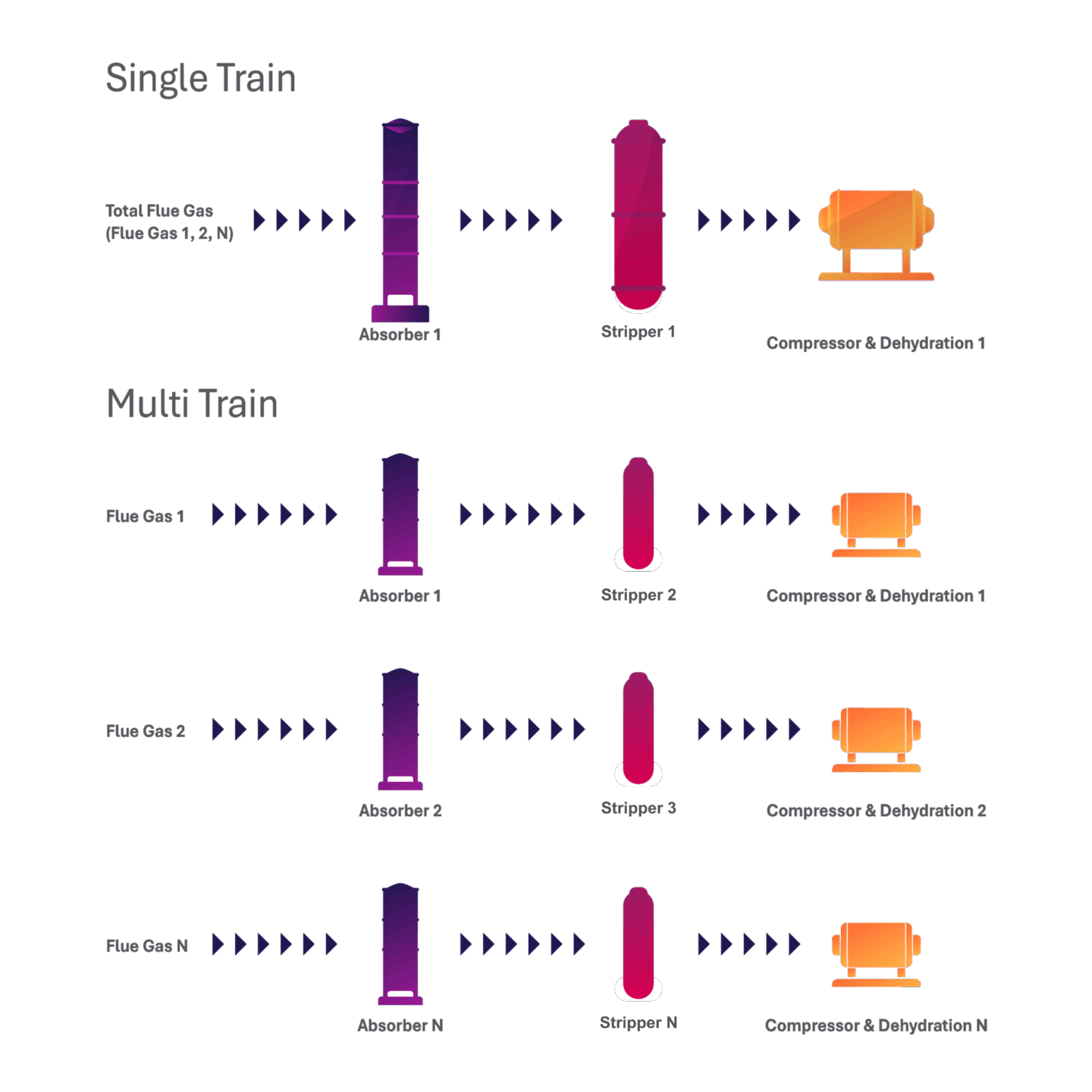
Single-train and multi-train systems are both viable options for capture projects, and an evaluation of the costs and benefits of each system is often necessary to evaluate the best option. The figures shown illustrate a comparison of a single-train and a multi-train system. It is important to note that there are variations of the multi-train system, such as multiple absorbers can be used to feed into a single stripper, which haven’t been captured in the figures.
In this study:
This study selected two carbon capture and compression trains, each containing a direct contact cooler (DCC), an absorber, a stripper, and a CO2 compressor. The ductwork from the new wet flue gas desulfurization (WFGD) system splits into two separate trains and is designed with dampers to isolate each train. Within each train, the major pieces of equipment, excluding vessels, will be sized at 50% capacity of the single train design. This arrangement allows for flexible operations of the carbon capture plant and provides risk mitigation so that one train can operate at partial load if any of the components need to be serviced.
Additional information:
The choice between these systems is influenced by both site-specific and project-specific factors. Below, we provide a comparison of multi-train vs. single-train systems.
Table 1: Comparison of Multi-Train vs. Single-Train Carbon Capture Systems
| Aspect | Multi-Train System | Single-Train System |
|---|---|---|
| Configuration (in this FEED study) | Two carbon capture and compression trains | One capture system handling all the flue gases |
| Prefabrication Potential | Higher – Allows for extensive off-site fabrication | Lower – Larger system components may limit prefabrication options |
| Construction Efficiency | Higher – Faster on-site construction due to shop fabrication | Lower – Longer on-site construction due to size and complexity |
| Project Schedule Certainty | Higher – Due to off-site fabrication of components | Lower – Due to on-site assembly and integration challenges |
| Transportation and Installation | Easier – Due to smaller, pre-assembled modules | More complex – due to size and integration of large equipment |
| Operational Flexibility | Higher – Independent operation of each train allows more turndown flexibility | Lower – Single system may limit flexible operation |
| Reliability and Maintenance | Higher – Online maintenance possible, increased uptime | Lower – Maintenance may require full system shutdown |
| Physical Footprint | Larger – Two systems require more space on site | Smaller – Consolidated system uses space more efficiently |
Reduction of Water Vapor in the CO2 Product via the Cold Rich Bypass
What is it:
In carbon capture systems, water vapor can remain mixed within the CO2 product stream. To ensure the integrity and safety of transportation and storage systems, water content must meet the set transportation and storage specifications, which typically requires very dry (low water vapour) and high purity CO2 (greater than 95 mol%).
In this study:
The Cold-Rich Bypass (CRB) is a design feature selected to minimize water vapor content. It works by diverting a portion of the cold, CO2-rich solvent from the absorber, bypassing the lean-rich heat exchanger and sending it directly to the top of the stripper column. When this cooler solvent enters the hot stripping zone, it helps condense water vapor into a liquid, facilitating water separation from the CO2 stream. This reduces the load on the glycol-based dehydration system which removes the water content from the CO2 to levels below the facility’s pipeline specification of 30 lbs H2O/MMscf.
Additional information:
The CRB method could be a more energy-efficient than relying only on additional dehydration equipment. It can help minimize the downstream dehydration load, reduce the size of dehydration equipment, and reduce energy use of the system.
Selection of a Concrete Absorber Lined with Stainless Steel
What is it:
In amine-based carbon capture systems, the CO2 absorber is a large vertical vessel where flue gas comes in contact with a liquid solvent, and the CO2 is absorbed into the solvent. As this vessel is one of the most expensive pieces of equipment within the carbon capture plant, it is important that it can withstand corrosive chemical exposure over long periods of time. While most pilot or small-scale CO2 absorbers are constructed from a single corrosion-resistant material, such as stainless steel, using stainless steel alone for a large-scale absorber may not be a cost-effective solution for these issues.
In this study:
Instead of being constructed entirely from stainless steel, the absorber in this FEED study was designed as a reinforced concrete structure lined with stainless steel. Cost and constructability considerations fed into the material selection decision. While using concrete alone may offer potential cost-savings, this material is susceptible to corrosion, particularly in acidic, high-moisture environments. To address corrosion concerns, stainless steel reinforcement and lining was incorporated to extend the structural lifespan of the absorber in aggressive service conditions.
Additional information:
Material selection for equipment is often a trade-off between cost and corrosion resistance. For example, selecting carbon steel for the absorber is significantly less expensive than stainless steel, but it requires internal linings or protective coatings for corrosion resistance. It is important to highlight that these linings can degrade over time. If the lining is damaged or fails, the exposed carbon steel becomes highly vulnerable to corrosion, particularly in environments that are wet, acidic, or contain chemical solvents.
While a reinforced concrete absorber lined with stainless steel, or a full stainless steel absorber adds to the upfront cost, its durability and resistance to corrosion help reduce long-term maintenance, making it a cost-effective choice over the plant’s operational life.
Optimization of Energy Consumption to Achieve Reboiler Duty <2.5 MJ/kg CO2
What is it:
In solvent-based carbon capture systems, reboiler duty refers to the amount of thermal energy required to regenerate the solvent and release the captured CO2. This is typically the largest single energy demand in a post-combustion capture plant and lowering the reboiler duty directly improves plant efficiency and project economics. Reducing reboiler duty involves optimizing thermal integration, solvent performance, and system configurations.
In this study:
In the FEED study, ION achieved a specific reboiler duty of less than 2.5 MJ/kg CO2, which is significantly lower than that of conventional MEA-based systems (typically ~3.2–3.6 MJ/kg CO2). Achieving this target marks a 30% improvement over traditional MEA systems.
While the report doesn’t include specific details, it identifies three key contributors to this energy reduction which are:
- Use of ICE-21 solvent
- Cold-Rich Bypass (CRB)
- Intercooling in the absorber
Additional information:
To enhance CO2 absorption and reduce energy consumption, amine intercoolers and heat recovery units from the CO2 compressor are used in carbon capture systems. The choice to include an intercooler and heat recovery would be based on a project-specific economic analysis, as incorporating these units involves additional capital costs.
Selection of the Electrodialysis Reclaimer for Degraded Amines
What is it:
In carbon capture systems that use chemical solvents like ICE-21 to absorb CO2 from the flue gas stream, the solvent gradually degrades over time due to heat, oxygen, and impurities in the flue gas. Degradation products accumulate within the solvent and can interfere with the system’s performance, causing corrosion, foaming, or reduced CO2 absorption performance. Amine reclaiming is necessary in carbon capture systems to remove these degradation products to maintain amine health.
In this study:
ION selected an electrodialysis (ED) reclaimer for the full-scale CO2 capture plant. Electrodialysis is a membrane-based, electrically driven separation process for amine reclamation. It works by removing the heat-stable salts and degradation products and replacing them with hydroxide. Most of the usable solvent is retained, while the waste is treated for nitrogen and directed to the wastewater treatment plant.
Additional information:
The report mentions using ED to remove heat-stable salt anions but does not specifically mention the cation and non-ionic degradation products. Definitions of these terms are provided below.
- The anion portion (e.g., formate, acetate, sulfate, nitrate) typically comes from acid gases or oxidative degradation of the solvent or flue gas contaminants.
- The cation portion usually originates from degradation products of the amine solvent, metal ions, or additives introduced into the system.
- The non-ionic degradation (e.g., formamides, aldehydes, amides) refers to the formation of neutral (uncharged) chemical species.
Typically, thermal reclaiming units are incorporated into amine-based carbon capture plant designs to remove the ionic and non-ionic degradation products. A small slipstream of the amine is heated in the thermal reclaimer, where the degradation products are separated from the water and amine due to the difference in their boiling points. The water and amine vaporize, and the degradation products are collected at the bottom of the reclaimer and removed. The vapor is then condensed and returned to the main amine loop for reuse. For future studies, a detailed understanding of the reclaiming design is required, particularly to assess whether a thermal reclaimer should be considered to remove both ionic and non-ionic degradation products.
Incorporation of a Hybrid Cooling System
What is it:
In thermal and chemical processing plants, such as an amine-based carbon capture plant, large amounts of heat must be removed from process fluids and utilities. Due to this, cooling systems are essential for removing the remaining heat.
The main types of cooling technologies available include:
- Wet cooling systems – such as cooling towers, wet surface air coolers (WSAC) use evaporation to dissipate heat. They are efficient but require makeup water to compensate for the water loss from evaporation and blowdown.
- Dry cooling systems – such as fin-fan air coolers rely on air flow alone and consumes no water but are less effective in hot climates. They also require more surface area and power than a wet cooling system.
A hybrid cooling system combines both technologies to balance water usage, cooling performance, and site-specific constraints.
In this study:
Due to the size of the cooling load, the existing once-through cooling water system from the host facility cannot be used for the capture facility as this may introduce permitting concerns and operational risks. To comply with site water usage and environmental constraints, the design team incorporated a hybrid cooling system that combines WSAC and fin-fan air coolers.
Additional information:
In a typical amine-based carbon capture process, a Direct Contact Cooler (DCC) is used to cool and scrub moisture from the incoming flue gas. This water is collected and can be reused as makeup water for the WSAC, thus improving water efficiency and reducing the need for freshwater intake.
Evaluation of two ownership models and their financial impact
What is it:
One of the critical early decisions when designing a large infrastructure project like a carbon capture plant is who will own and operate the capture facility. Operational responsibility is important as it affects capital cost, financing, tax obligations, insurance, staffing, and long-term operations.
Two common ownership models are:
- Host Site Ownership – The host plant owner (in this case, NPPD) builds and operates the carbon capture facility.
- Third-Party Ownership – An independent company owns and operates the carbon capture facility and sells the CO2 removal service to the host plant owner.
These models differ significantly in terms of cost structure, risk profile, and regulatory exposure.
In this study:
The FEED study compared both ownership models in terms of their impact on the levelized cost of capture (LCOC), capital investment, and operating expenses. It was found that host Site ownership results in a lower capital cost and benefits from public utility tax exemption (no property tax and lower insurance). It also leverages existing infrastructure for power, water, and staffing.
On the other hand, the third-party ownership shows a higher LCOC ($35 USD/tonne vs $49.90 USD/tonne). The third-party owner is subject to pay taxes, insurance, and must build standalone infrastructure such as their own cooling system, power substation, and water supply.
Additional information:
Even though the third-party ownership results in a higher LCOC than host site ownership, it can offer several strategic advantages, such as:
- Attracting private investment or government funding that might not be available to a publicly owned utility.
- Reducing operational burden on the host utility, which may be preferred to avoid managing the additional complexity of the capture system.
- Separating business and liability risks between the power generation and carbon capture operations, offering clearer accountability and risk management for each party.
This structure can be especially appealing in scenarios where decarbonization is pursued through partnerships or financed independently from the base power asset.
Evaluation of integrating BECCS to offset 10% of GGS2’s remaining CO2 emissions
What is it:
Bioenergy with Carbon Capture and Storage (BECCS) is a negative emissions technology that involves using biomass (i.e. forestry residues, agricultural byproducts, dedicated energy crops, and the biogenic waste used in Energy-from-Waste facilities) as a fuel source to generate energy in the form of heat, electricity or fuels.
Since biomass absorbs CO2 during its growth, capturing and sequestering the emissions when it is used for energy production results in a net removal of CO2 from the atmosphere, leading to negative emissions. One way to implement BECCS at a coal-fired power plant is to co-fire the biomass with coal, partially replacing the coal feedstock.
In this study:
The FEED study explored the integration of a biomass gasification system to generate syngas from corn stover, which is a biomass feedstock sourced from agricultural residues. The syngas would be co-fired with coal in the existing boiler to offset roughly 10% of fossil fuel use. The estimated additional cost of CO2 capture with BECCS is $24 USD/tonne CO2. When combined with the capture system, BECCS enables near net-zero site emissions during operations.
Additional information:
For additional information on BECCS, refer to the BECCS 101 section of the CCUSIA.
The CCUS Insight Accelerator (CCUSIA) is a partnership between the Government of Alberta and the International CCS Knowledge Centre to accelerate and de-risk CCUS by sharing knowledge and developing insights from projects.