FEED Study Introduction
The US Department of Energy (DOE), through its Office of Fossil Energy and Carbon Management (FECM) has funded several Front-End Engineering and Design (FEED) studies for retrofitting existing fossil fuel power plants with carbon capture technology. These comprehensive studies are publicly available on the US DOE Office of Scientific and Technical Information (OSTI) website as part of the knowledge-sharing requirements associated with the funding.
This study is our effort to help stakeholders quickly understand the key findings in lengthy reports, highlighting methodologies and unique design aspects that could shape future carbon capture plant designs. Our objective is to highlight the most relevant sections of each study.
Integrated Water-Gas-Shift Pre-Combustion Carbon Capture
Overview
This FEED study, conducted by TDA Research in collaboration with the Gas Technology Institute, University of California Irvine, and Praxair (now Linde), examines the deployment of a pre-combustion carbon capture process, using integrated water-gas-shift (WGS) and pressure swing adsorption (PSA). The purpose of this study is to assess the techno-economic viability and performance advantages compared to conventional, solvent-based capture technologies.
To demonstrate this, two theoretical host configurations were modeled:
- An Integrated Gasification Combined Cycle (IGCC) power generation unit, achieving a net power output of approximately 553 megawatts electric (MWe).
- A Fischer-Tropsch (F-T) fuel production facility, designed to produce approximately 5,110 tonnes/day of synthetic fuels (1,509 tonnes/day of naphtha and 3,601 tonnes/day of diesel), while producing 253 MWe of co-generated power.
Both theoretical host configurations were modelled using ConocoPhillips’ E-Gas™ and General Electric’s GEP type gasification systems. These configurations were based on DOE/NETL baseline studies, specifically DOE/NETL-2010/1397 Rev 2a for IGCC power generation and DOE/NETL-2011/1477 for Fischer-Tropsch liquids, which represent optimized configurations derived from several reference plants.
This study includes a detailed process design and techno-economic analysis, comparing both host configurations integrated with WGS and PSA capture processes (i.e., warm gas cleanup) against a conventional, solvent-based capture process (i.e., cold gas cleanup). In addition, a 10 standard cubic feet per minute (SCFM) pilot unit was built and tested to demonstrate the integrated process under realistic operating conditions.
FEED study link: Integrated Water-Gas-Shift Pre-Combustion Carbon Capture
Total CO2 captured: Approximately 3.5 MM tonnes/yr for the IGCC power generation unit, and 8 MM tonnes/yr for F-T fuel production facility. These values were not stated in the FEED report but were estimated based on heat and material balance at an assumed 90% capacity factor.
Total As-Spent CAPEX for a new greenfield facility with carbon capture ($MM USD in 2011):
- IGCC power generation unit: $1,658 – $1,804
- F-T fuel production facility: $5,000
Objective
This summary highlights the unique design and planning aspects of this FEED study, which include:
- Integration of water-gas shift reaction and CO2 capture in a single warm gas reactor system for an IGCC
- Full scale plant performance evaluation
- Economic comparison of warm gas vs. cold gas cleanup
- Testing Results of an Integrated WGS and High-Temperature PSA based CO2 Capture Pilot Plant
- Validation of reactor performance using computational fluid dynamic modeling and experimental data correlation
Integration of Water-Gas Shift Reaction and CO2 Capture in a Single Warm Gas Reactor System for an IGCC
What is it:
The WGS reaction is a chemical process that turns carbon monoxide (CO) and steam into carbon dioxide (CO2) and hydrogen (H2). The industrial processes where this occurs are steam methane reforming, auto thermal reforming, and gasification (to learn more about these processes, visit Pre- and Post-combustion Carbon Capture). Traditionally, CO2 is captured in a separate unit downstream of the WGS reactor, but TDA Research has developed a more efficient approach, integrating CO2 capture with a second-stage WGS reactor in a single, compact, high-temperature system.
In this study:
TDA Research’s Integrated WGS pre-combustion carbon capture system uses a two-stage shifting strategy comprised of:
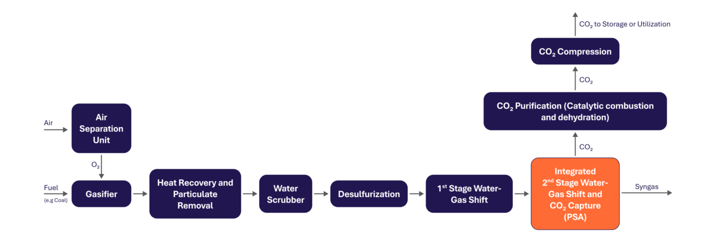
- 1st Stage Water-Gas Shift: A standalone WGS reactor containing a commercial catalyst that converts most of the CO into H2 and CO2.
- Integrated 2nd Stage Water-Gas Shift and CO2 capture (shown in orange): Includes a WGS reactor with a catalyst to further convert residual CO into H2 and CO2, along with a high-temperature CO2 scrubber that uses PSA to capture the CO2 as it is produced.
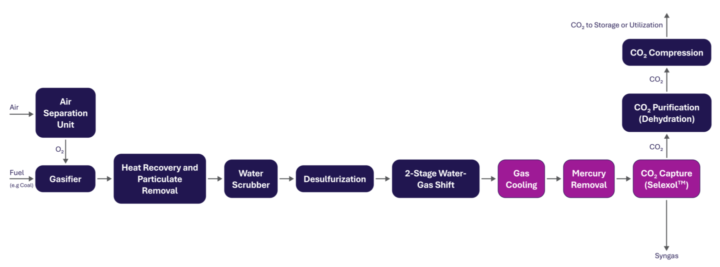
In a conventional cold gas cleanup system with carbon capture, the gas exits 2 stages of WGS and is then cooled and treated for mercury removal, prior to entering an absorber where CO2 is captured using a liquid solvent, such as SelexolTM.
The 2nd stage integrated unit, shown in orange in Figure 1, operates at temperatures between 200–400°C, which is a benefit for the integrated process. Operating at these higher temperatures eliminates the need for costly cooling to ~35°C for CO2 separation, which is required in conventional cold-gas cleanup systems, as shown in Figure 2. Instead, the second stage integrated unit enables CO2 capture directly during the high temperature WGS reaction. In this unit, the CO2 adsorbent and the WGS catalyst work together to simultaneously drive the chemical reaction and capture the CO2 as it forms. Because the CO2 is removed as soon as it forms, the reaction becomes more efficient, producing more H2 while also reducing steam demand, as the system does not need as much for the reaction to occur. Overall, the warm gas cleanup integrated approach reduces energy use and lowers operating costs compared to conventional cold gas cleanup systems.
The table below compares key performance metrics between the conventional cold gas cleanup configuration with CO2 capture and TDA Research’s warm gas cleanup with CO2 capture technology for an IGCC.
|
Metric |
Conventional Cold Gas Cleanup |
Warm Gas Cleanup (TDA Research Technology) |
|---|---|---|
| Process Configuration | Separate two-stage WGS and CO2 capture system | 1st Stage WGS and TDA Research’s integrated 2nd Stage WGS and CO2 capture system |
| CO2 Capture Technology | Selexol™ Solvent-based capture system | High-temperature PSA capture system |
| Operating Temperature for CO2 Capture Unit | Low temperature (~35°C) | High temperature (~200–300°C) |
| Steam Requirement | Higher (H₂O:CO ratio ~2.0) | Lower (H₂O:CO ratio ~1.0) |
| Net Plant Efficiency (HHV) | ~30.9–31.9% | ~34.4–34.9% |
| CO2 Purification Method | CO2 dehydration | Catalytic combustion with pure O2 and CO2 dehydration |
Additional information:
An example of an operational cold gas cleanup system is the Wabash River IGCC plant in Indiana, USA. It uses Selexol to remove CO2 after gasification. While effective, this method requires substantial steam for the water-gas shift reaction and significant cooling energy to reduce the temperature of the syngas to the temperatures required for Selexol absorption, increasing the project’s capital cost and operating expenses.
Full-Scale Plant Performance Evaluation
What is it:
An evaluation of the full-scale plant performance looks at how new technologies would work when scaled from a small pilot setup to a full commercial power or industrial plant. Researchers use these process simulations to predict how a technology would perform in actual systems.
In this study:
The research team combined results from their pilot-scale tests with Aspen Plus® modeling to simulate a commercial-scale IGCC plant and F-T fuel production facility using the newly integrated WGS and CO2 capture system.
They analyzed six different case studies to evaluate performance across various gasifier types and process setups. The results, summarized in the table below, show that the technology is not only technically feasible but also economically competitive for large-scale carbon capture applications.
| Case | Gasifier Type | Cleanup Type | Application/Product | Key Features | Net Efficiency (%HHV) | CO2 Capture Cost ($/tonne) |
|---|---|---|---|---|---|---|
|
Case 1 |
E-Gas™ | Cold Gas Cleanup | IGCC Power Generation / Electricity | Selexol-based CO2 Capture, Conventional WGS | 30.91% | 42.6 |
| Case 2 | E-Gas™ | Warm Gas Cleanup | IGCC Power Generation / Electricity | Integrated WGS + PSA, Catalytic CO2 Purification | 34.45% | 25.9 |
| Case 3 | GE gasification | Cold Gas Cleanup | IGCC Power Generation / Electricity | Selexol-based CO2 Capture, Conventional WGS | 31.90% | 37.5 |
| Case 4 | GE gasification | Warm Gas Cleanup | IGCC Power Generation / Electricity | Integrated WGS + PSA, Catalytic CO2 Purification | 34.86% | 28.1 |
| Case 5 | E-Gas™ | Cold Gas Cleanup | Fischer-Tropsch / Fuel Production and Electricity | Rectisol, PSA for H2, Conventional CO2 Capture | 2.33% (power export) | Not Provided |
| Case 6 | E-Gas™ | Warm Gas Cleanup | Fischer-Tropsch / Fuel Production and Electricity | Integrated WGS + PSA | 4.23% (power export) | Not Provided |
Additional information:
Designing a carbon capture plant is complex and costly. Simulation software plays a critical role in testing different operating conditions, equipment sizes, and chemical interactions. These results help predict a design’s full-scale performance and uncover opportunities for projects to reduce costs and mitigate risks.
In this study, Aspen Plus® was used to model the integrated WGS and CO2 capture process. The model was developed based on the pilot plant data, making it a reliable tool for projecting commercial-scale outcomes. While Aspen Plus® was the primary tool here, other widely used simulation platforms in industry and academia include Aspen HYSYS, gPROMS, ProTreat®, Pro/II, CHEMCAD, and DWSIM.
Economic Comparison of Warm Gas vs. Cold Gas Cleanup
What is it:
CO2 can be captured from the gasification system using two main process approaches: cold gas cleanup and warm gas cleanup. For pre-combustion capture, cold gas cleanup is a process where the gas is cooled to approximately 35°C before using a liquid solvent, such as Selexol, to absorb CO2 under high pressures. The CO2-rich solvent then needs to be depressurized and heated to release the CO2, with the solvent being recycled back to the system to capture more CO2. On the other hand, warm gas cleanup keeps the gas at higher temperatures for capture using PSA capture technology.
In this study:
TDA Research compared the warm gas cleanup system with a conventional Selexol cold gas cleanup system in both integrated full-scale IGCC and F-T plant scenarios. Using Aspen Plus modeling and DOE/NETL cost methods, TDA Research analysed six different case studies as described previously.
Here are the key findings:
- Capital costs were 6-13% lower with the warm gas system.
- CO2 capture cost fell from about:
- $43/tonne (cold gas cleanup) to $26/tonne (warm gas cleanup) for E-Gas™ case
- $38/tonne (cold gas cleanup) to $28/tonne (warm gas cleanup) for GE gasification case
- Both excluding CO2 transportation, storage, and monitoring (TS&M) costs
- The warm gas system is also a simplified plant design due to combining CO2 capture and chemical conversion into one unit.
Additional information:
Selexol is a commercial physical solvent system developed by UOP (Honeywell) and has been widely used in large-scale gasification since the 1980s. Examples include Dakota Gasification Plant in North Dakota, where Selexol is used to capture over 3 million tonnes of CO2 per year for enhanced oil recovery (EOR). While proven and reliable, Selexol process requires extensive cooling and energy which make it more costly and complex to integrate into gasification plants.
Testing Results of an Integrated WGS and High-Temperature PSA based CO2 Capture Pilot Plant
What is it:
A pilot plant integrating a WGS and high temperature PSA CO2 capture system is a small‑scale, fully integrated version of the process, allowing researchers to test the new technology under realistic operating conditions. The pilot unit processes syngas at conditions that closely match those inside a commercial gasification facility. By running the system at this scale, researchers can verify how the reactor, sorbent materials, and high‑temperature PSA system perform together during start‑up, steady‑state operations, and thousands of adsorption/regeneration cycles.
In this study:
TDA Research and the University of California built and tested a pilot-scale unit using the integrated design. The system operated at a temperature range of 300-400°C, and pressures up to 30 bar, which matched the conditions found in the actual gasification operation.
Key findings from the pilot testing include:
- At a steam/CO ratio of approximately 1.0, over 96% of CO was converted into H2 and CO2. This outperforms conventional systems, which typically achieve 92 – 95% conversion but require a steam/CO ratio of about 2.0.
- Traditional systems, such as Selexol, are described as equilibrium-limited and do not remove CO2 during the WGS reaction. It limits how far the reaction can proceed toward converting CO to H2.
- More than 90% of the CO2 was captured.
- The pilot-scale testing proved the system to be durable, maintaining a stable performance over 30,000 test cycles.
Additional information:
TDA Research’s technology replaces two large pieces of equipment with one compact unit, making it easier and less expensive to design, build, and operate. It is also modular, meaning multiple units can work together, or while one unit is being cleaned or maintained, others can continue operating.
Traditional amine-based carbon capture needs a significant amount of energy to regenerate the solvent as well as large absorber and regenerator towers. TDA’s system avoids these challenges by working at higher temperatures and using solid materials to capture CO2. These innovations are key reasons why the system offers lower costs, higher H2 production, smaller equipment, simpler operation, and improved energy efficiency.
Validation of Reactor Performance Using Computational Fluid Dynamic Modeling and Experimental Data Correlation
What is it:
Before engineers can confidently scale up a new reactor design for industrial use, they need to ensure it performs reliably under actual operating conditions. This process, known as performance validation, assesses whether predictions from computer simulations accurately reflect observed performance from testing.
One of the key tools used for this process is Computational Fluid Dynamics (CFD). CFD allows researchers to simulate how gases move, react, and transfer heat inside the reactor. It provides a detailed visualization of the temperature, pressure profile, and reaction zone, providing insights that are difficult to measure during experiments.
By comparing CFD results with data from laboratory or pilot-scale tests, researchers can confirm if the model accurately reflects how the reactor behaves in an operational environment. Once validated, the model becomes a powerful tool for predicting larger-scale performance, helping reduce cost and mitigate risk during scale-up.
In this study:
In this project, TDA Research Analysis used Ansys Fluent for CFD modeling to validate the single unit’s high-temperature PSA reactor and CO2 capture performance. TDA built the pilot-scale reactor to handle 10 scfm of gas.
CFD simulations were run to model the gas flow, temperature distribution, and chemical reactions inside the reactor bed. The simulation results were compared to actual measurements from the pilot tests, including temperature readings, gas concentrations, and H2 output.
The model matched the experimental data very closely within ±5%, confirming its accuracy. CFD also helped visualize how heat was distributed and showed that the reactor design avoided hot spots. With the validated model, the team fine-tuned the reactor’s configuration, gas flow paths, and timing of pressure swings, all of which informed the design for full-scale commercial units.
Additional information:
Unlike conventional CO2 capture systems, like Selexol which can rely on decades of operating data, this new high-temperature PSA reactor is a first-of-its-kind design with complex gas-solid interactions. Considering CFD ensures the design is operating safely, reliably, and efficiently.
Ansys Fluent allowed the team to view the behavior of the reactor from inside, showing how gases flow through the packed bed, how heat is managed during adsorption and desorption, and how the system behaves during cyclic operation. Using CFD simulation with the actual testing can reduce uncertainty and avoided costly overdesign, saving time and money during the scaled-up design.
The CCUS Insight Accelerator (CCUSIA) is a partnership between the Government of Alberta and the International CCS Knowledge Centre to accelerate and de-risk CCUS by sharing knowledge and developing insights from projects.