Who remembers learning about the three R’s in grade school??? Reduce! Reuse! and Recycle! This simple concept aimed at reducing tangible wastes can also be applied to more abstract concepts such as, believe it or not, heat! Heat can be recycled by practicing good heat integration strategies. Heat integration is a study of how to minimize the amount of energy consumed while maximizing the amount of heat that is recovered during a heat transfer exchange process. It is a system that is essential for the design and engineering of successful power plant carbon capture and storage (CCS) retrofits.
This blog, based on my abstract (read full abstract here), is part of a feasibility study to optimize the steam cycle heat integration process, and in particular, the use of condensate preheating (CPH) to lower the energy penalty experienced with a fully integrated CCS, scale-up retrofit. Essentially, we want to minimize the impact that capturing carbon has on a power plant’s ability to produce electricity by being more efficient in how we reduce, reuse and recycle heat.
CCS technology requires steam for amine regeneration. This steam can come from within the power plant (integrated design resulting in an electricity output penalty) or from an external dedicated steam supply (increased capital costs). The integrated approach was used in SaskPower’s Boundary Dam 3 Carbon Capture and Storage Facility (BD3), the world’s first fully integrated CCS retrofit of a coal-fired power plant. BD3 is unique in design and has heavily informed our work at the International CCS Knowledge Centre. Learnings from BD3 have provided the foundation for our feasibility study of SaskPower’s Shand Power Station – a second-generation CCS project that will be more efficient and more economical.
SaskPower’s Shand facility is a 300 MW, single unit, coal-fired power plant producing approximately 1,100 kg of CO2/MW-h. Shand’s capacity is twice that of BD3’s – making it an ideal candidate for a large-scale, CCS retrofit.
How a Power Plant Works
Before we dive into our findings, let’s take a look at the regular workings of a power plant. In simple terms, steam exits the boiler, passes through the turbines, expands, loses heat, and then enters the condenser. At this point the steam is essentially water and is referred to as condensate. This condensate passes through a series of feed water heaters, which use steam extracted from the turbine to warm up the “cold” condensate before it re-enters the boiler. Having the condensate re-enter the boiler “pre-heated” and in a “warm” state is optimum because the boiler doesn’t have to work as hard, making it function more efficiently.
What Happens When We Add a Carbon Capture Facility?
Things change when the power plant must function with the added relationship of a carbon capture facility that draws on the power plant for steam as part of the capture process. The flue gas that exits the power plant is very hot and must be cooled before entering the capture facility to work properly with the amine (the solvent used to capture the CO2).
The heat that is rejected from the flue gas via the flue gas cooler (FGC) is essentially transferred to water, producing a hot circulating stream. This hot circulating stream flows to three Condensate Pre-Heaters (CPH 1,2 and 3).
The difference between BD3 and Shand is that in BD3 there is one large CPH that is in parallel with the LP (low-pressure) heaters, as opposed to the 3 CPHs that are in series orientation with low-pressure feed water heaters 1 and 2 (LP FWH 1 and 2). This means that LP FWH 1 and 2 are completely by-passed during capture operations (i.e. the condensate does not flow through them at all). In this case, if the FGC suddenly goes off line, the stream of hot water flowing to the CPHs becomes cold and no longer supplies heat to “warm up” the condensate. The condensate then enters the deaerator (DEA) in a “cold” state, forcing the DEA to extract a larger amount of steam to warm it up. This scenario continues until LP FWH 1 and 2 can be put back into service – causing stress on the system.
Reusing Heat and Reducing the Output Penalty via Condensate Preheating Flexibility
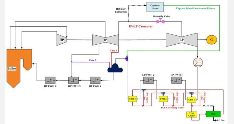
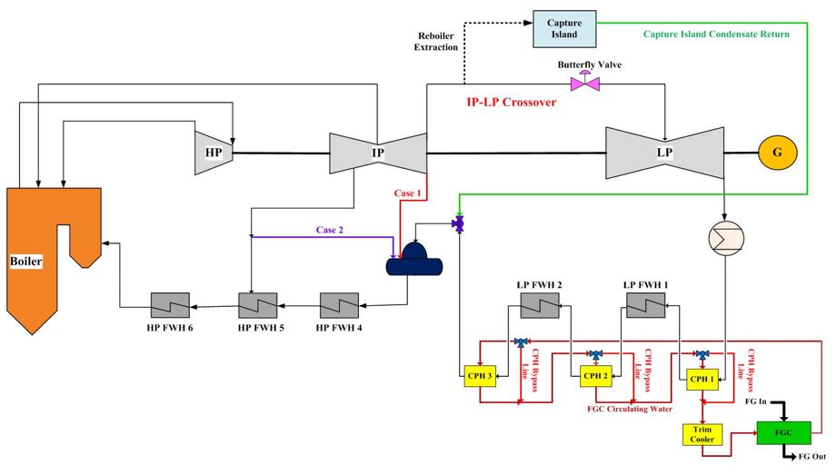
In our Shand model, we proposed that these CPH be arranged in series with the LP FWH 1 and 2, see Figure 1. The five of them together, (LP FWH 1 & 2 and CPH 1,2, and 3) work to “warm up” the condensate by primarily using the rejected heat from the flue gas.
FWH 1 and 2 remain in service during capture operations, but only function at a 5% capacity in order to ensure the steam is flowing in the correct direction, and that the heaters are warm and ready for service, if required. In other words, the amount of steam they continue to extract from the LP turbine for “pre-heating” purposes is minimal. This way, if the FGC shuts down, the loss in heat that was being supplied by CHP 1,2 and 3, will be easily compensated by LP FHW 1 and 2, since the condensate is already flowing through them. LP FHW 1 and 2 will recognize the colder condensate stream entering the system and will revert to extracting the usual amount of steam from the turbine to warm up this suddenly “colder” stream.
This new heat integration method eliminates any stress that may be experienced by the DEA. Overall, this new configuration of the CPH train lowers the energy penalty by reusing the maximum amount of rejected flue gas heat and limiting the amount of steam extracted. More importantly, this configuration continually adapts to changing amounts of unit load, which is one of the features that allows this carbon capture plant to integrate with variable renewable energy sources like wind and solar.
It has been exciting to be part of this International CCS Knowledge Centre study to demonstrate that the second generation of CCS technology can be more efficient, cost effective and flexible.
– – – –
For more blogs on advancements to 2nd generation CCS, see: