In a hybrid car, electricity and fuel combustion are two different processes that are combined in a complimentary way to reduce the emissions profile of a car. With a hybrid cooling system, both dry and evaporative cooling can be implemented in a complimentary manner to offer a solution to reduce the water intake and its consumption for the power plant’s cooling system.
On it’s own, a coal-fired power plant is designed to continuously recycle and cool water and steam internally. When we add a large-scale carbon capture facility, the combined systems generate a volume of heat and water that the existing cooling system of the power plant is incapable of rejecting on its own.
At the International CCS Knowledge Centre, we are committed to eliminating barriers, either real or perceived, that inhibit large-scale, CCS development. Since the availability of cooling is generally one of the first design concerns for siting a thermal power facility, and quite often ends up being the limiting factor for further expansion at a given site, we anticipate that the availability of cooling capacity can often impede the addition of CCS to a facility.
This cooling challenge formed the basis of a study we conducted, (see full study abstract here) which sought to design an additional cooling system for a CCS retrofit of SaskPower’s Shand Power Station (Shand). Shand is a 305 MW, single unit, coal-fired power plant producing approximately 1,100 kg of CO2/MWh. Shand’s capacity makes it an ideal candidate for a large-scale, CCS retrofit.
Shand draws water from three main sources: the Rafferty Dam, a secondary treated sewage water stream from the nearby city of Estevan (after passage through a Constructed Wetland) and a yard drainage system that collects melted snow, rain and runoff. These water supplies are used in the plants cooling tower to reject 425.7 megawatts thermal (MWth) of heat. There is limited water in the area, and a draw on additional water (for increased heat rejection capacity) is not anticipated to be possible and is likely a consideration for many power plants around the world.
So how does CCS change the heat rejection profile of a power plant? The addition of an integrated capture plant actually reduces the amount of heat rejected by the power plant, because some of the steam is being drawn to the CCS facility for its use. Figure 1 illustrates a drop in the heat to be rejected from the power plant from 425.7MWth to 306.5MWth. Since there is less heat from the power plant, the carbon capture facility can reject some of its excess heat to the cooling tower, but the cooling tower doesn’t have the capacity to manage the entire volume coming from both systems.
The illustration in figure 1 below, indicates that after the capture plant rejects 97.8 MWth to the power plants cooling tower 242.5 MWth is still left.This quantity of heat is approximately a 50% overall increase in the amount of heat that the existing power plant must reject.
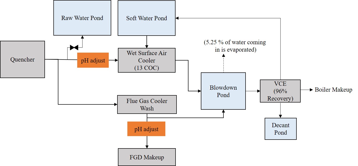
During capture operations, flue gas must be cooled prior to the CO2 capture reaction. This cooling condenses water out of the flue gas at a rate of approximately 97.5 tonnes/hr. In order to maintain zero liquid discharge (ZLD) of the plant, this water can be used for cooling but it isn’t nearly enough as this stream of condensed water can only reject 40% of the excess heat, leaving 60% that still needs rejecting. This problem inspired the design of a hybrid cooling system consisting of dry air coolers and wet surface air coolers (WSAC) connected in series as a solution.
The new hybrid system’s design is based on 18deg C dry bulb and 13.7deg C wet bulb temperatures, which is the 85th percentile of the historical temperature from 1991 to 2005 in the Estevan area (Environment Canada Data). Though more CO2 can be captured at low ambient temperatures, de-rates of the CCS facility are viewed as still being acceptable at high ambient temperatures. Setting the design case at the 85th percentile decreases design margins, avoids oversizing the system and saves costs. Overall, the heat load on the dry air cooler and WSAC is 66% and 34% MWth, respectively. The power consumption at the design condition is 3.91 megawatts electric (MWe) for dry air cooler and 1.01 MWe for WSAC.
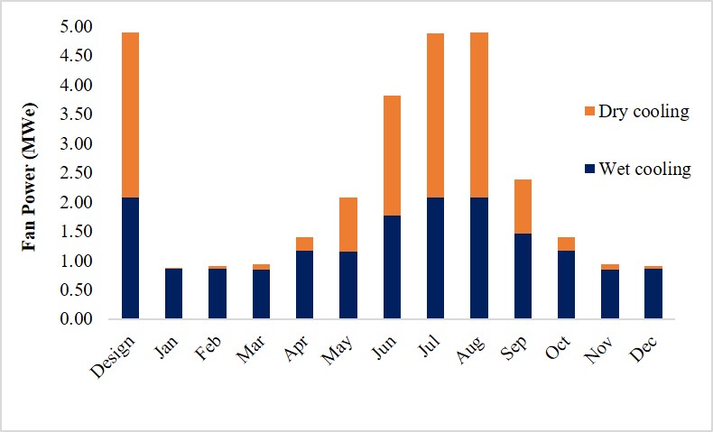
A major challenge in western Canada is that ambient temperatures can range from +40deg C to -40deg C. To compensate for this range, we designed the system so that both the dry air cooler and WSAC have variable frequency drives which allows them to adjust the relative amount of overall cooling to match ambient conditions. This allows the heat rejection to be shifted between wet and dry cooling, so that the system can adjust the amount of cooling that is evaporative in order to maintain the water balance on the site.
We were curious about the effect that the varying temperatures, over a calendar year, might have on fan power consumption. It turns out that the consumption is only 40% of the design case, which is a bonus because this low energy cooling results in more power being able to be sold from the plant.
The effect of +40deg C to -40deg C on a Hybrid Cooling System
Our new hybrid design cooling system study provides a solution to the cooling challenge for new CCS facilities, and demonstrates how to maintain a zero liquid discharge facility. The International CCS Knowledge Centre will continue to champion solutions to advance the development of large-scale CCS facilities to reduce greenhouse gas emissions for our planet.
– – – –
For more blogs on advancements to 2nd generation CCS, see: